Designing the board.
I used Eagle to design the board, the software was easy to use and look really neat. It wasn't my first time with designing pcb, but I normally do really simple thing and use a software call sprintlayout But since Eagle as been recomended to me from a lot of people I decide to try it.
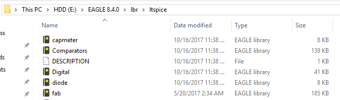
First thing I did was to go and download the fabacademy library (fab.lbr) Once the library was download I insert it in my Eagle lbr folder :
After loading the library I went inside it using the add command and import every component I needed for my board. I add a led a resistance and a button from the basic components of the helloboard as shown here:
Here is the list:
Attiny44
Ftdi Header
LED
Pressbutton
10k resistances
1 uF capacitors
499Omhs resistor
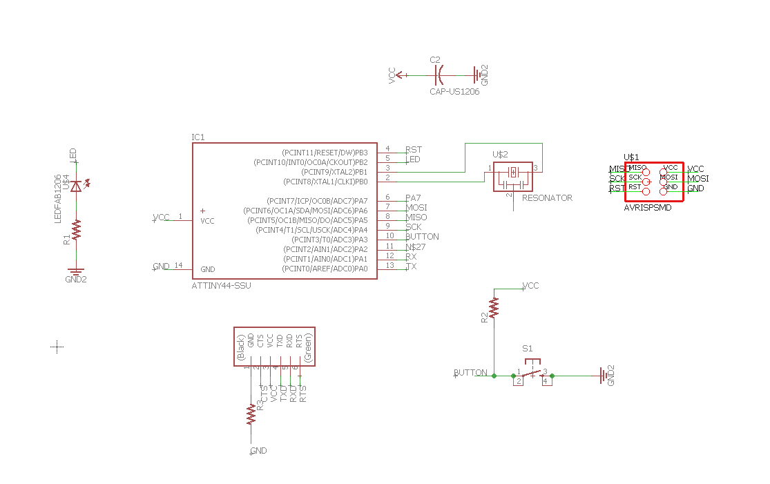
Then to link them I use two different method, I wanted the schematics to be clean so instead of link everything with a net trace I named my component and label them using the name and label command so they could be link with their names.
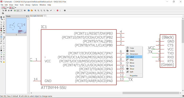

While the components that was near each other, I just used the normal net trace function and link them together.
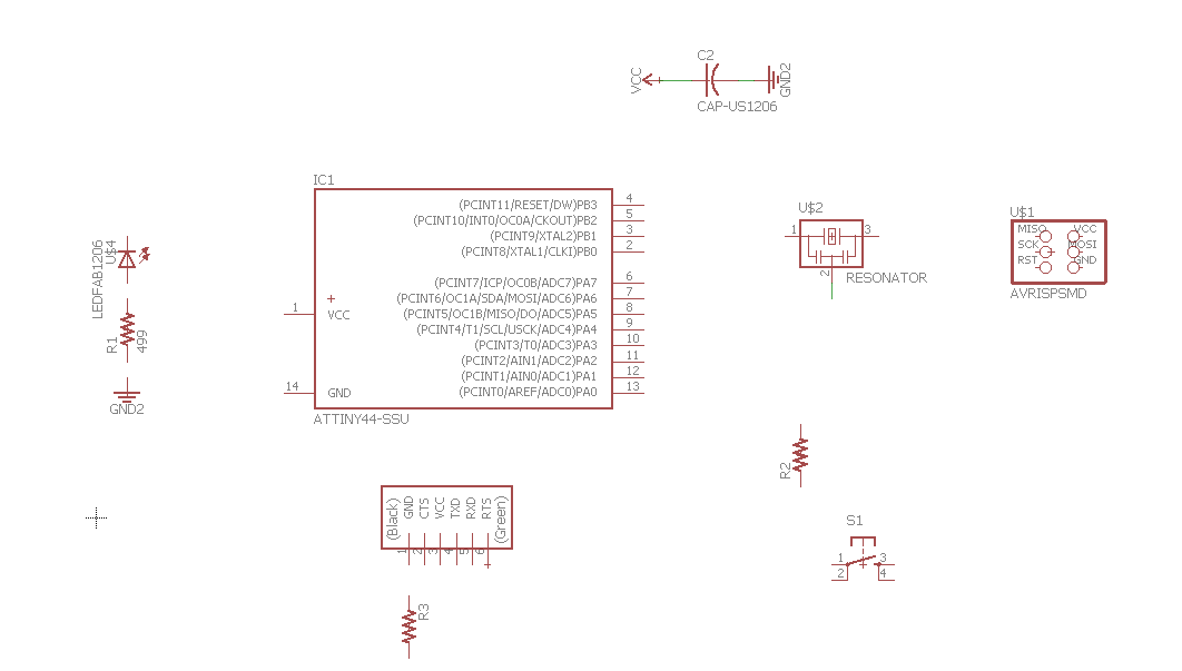
Once everything was in order Here what it looks like:
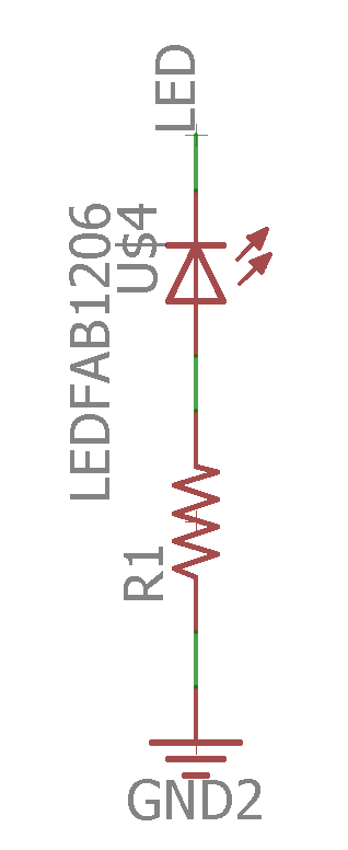
To know wich resistance value I had to use for my led, I simply took the datasheet of my led and determine the voltage and current needed for my LED.
I knew that I had to use this simple math to guess wich resistance I should use:
R=(powersupply voltage - LED Voltage) / Desired LED Current.
R=(5V - 2.2V) / 20mA = 220omhs.
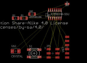
I then made the board by pressing the button Generate/Switch to board. Everything was messed up, but it was all there.
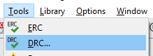
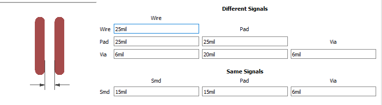
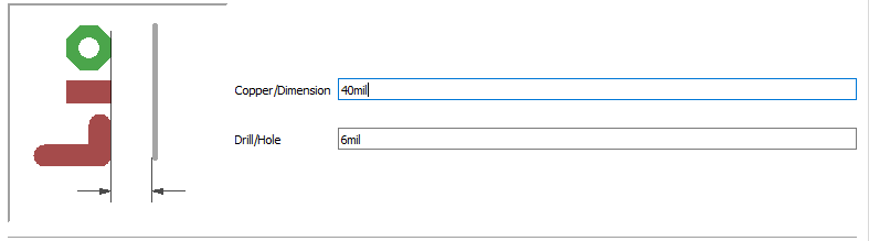
At first, I use the route function and try to make the trace by myself, it is possible but it's quite time conssuming, and it's like a puzzle, this is for a really simple board, I can't imagine for when our board will get more complex, so I didn't lose time and decided to try the autorouter tool. So First I needed to set my parameters into the DRC Tool. To make sure that the space between my trace would be ok, I set a space a bit bigger than the one between the pad of the attiny.
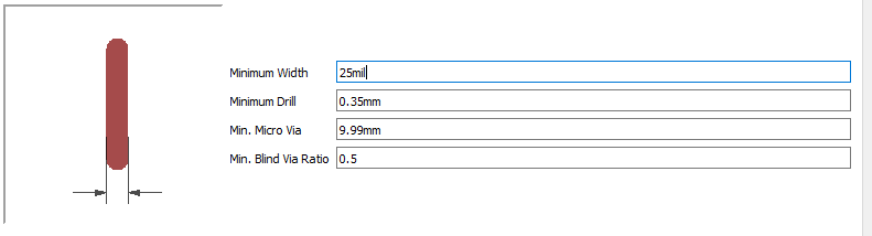
And I gave a with of 25mil for the interior of my traces.
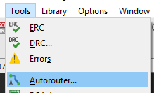
I then start the autorouter tool and let the magic happen!
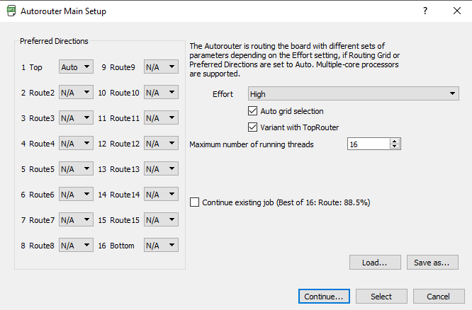
Inside the autorouter, you have to specify that you want a one layer PCB, then you just have to launch it, it will try different options for your traces and will tell you the percentage of completion of paths on every option so you can choose the better one, for a simple board such as the hello board it wasn't hard for it to find a 100% option.
Once the board was done, here what it looked like!
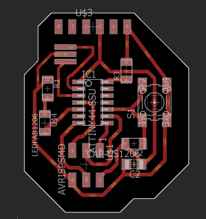
Designing PCB's is really fun and I totally fell in love with eagle, favorite week so far!
Preping the Gcode and Milling the board
Milling the board went pretty well, I didn't use the fabmodules this time, instead I used flatcam I'm in love with this software. It takes gerber and Excellions files and convert it into GCODE, the program is super user friendly, Have a amazing interface and is opensource!
The gerber format is an open ASCII vector format for 2D binary image, it is also the standart for PCB industry software and manufacturing.
First thing first I had to generate my gerber file from eagle and import it into Flatcam. This is really easily achieve my using the CAM processor inside Eagle software.
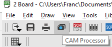
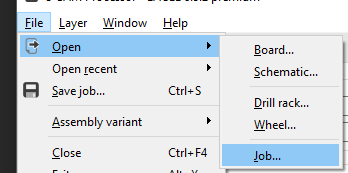
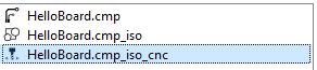
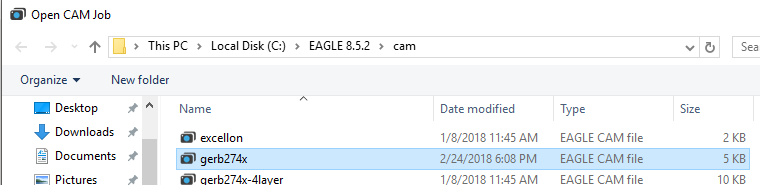 Eagle has already a Gerber file converter that brings your board into a gerber format. for a single layer PCB you load the CAM file named gerb274x. The you just have to process the job and it will save you a .cmp file into your eagle project folder.
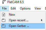
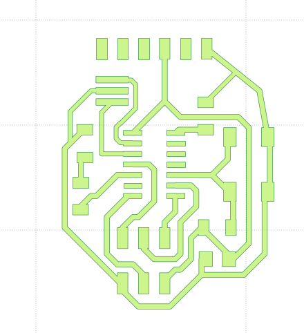
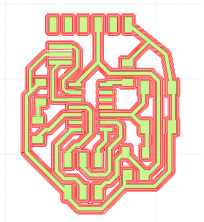
You can now open flatcam and open the .cmp file using the open gerber file.
You will see you board route appear!
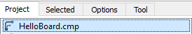
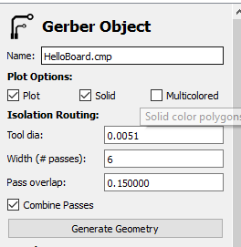
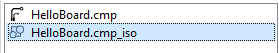
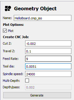
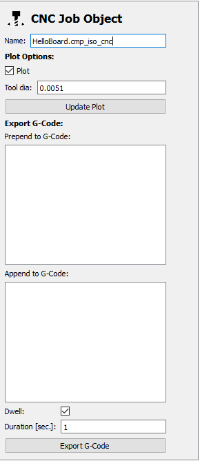
The rest is pretty straightforward, you will see in the left panel your job appear, click on it and go into the selected tab. Choose your isolation routing settings and generate the geometry
Then go back into the main panel and select the newly create route.iso job into the left panel.
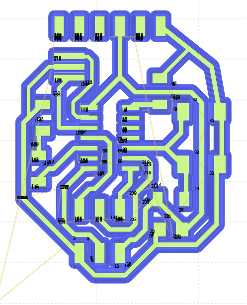
Finally, you can go and generate your gcode using the same method we just did twice
Flatcam is really great, now let's go to the machine! I bought myself a 2' / 3' cnc router that I will use for the board making. Here is the machine :
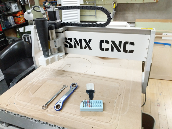
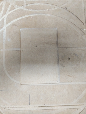
One thing I did before doing anything else is to make a square the size of my copper plate inside my sacrificial material (MDF) to make sure the bed is correctly level.
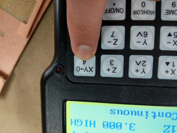
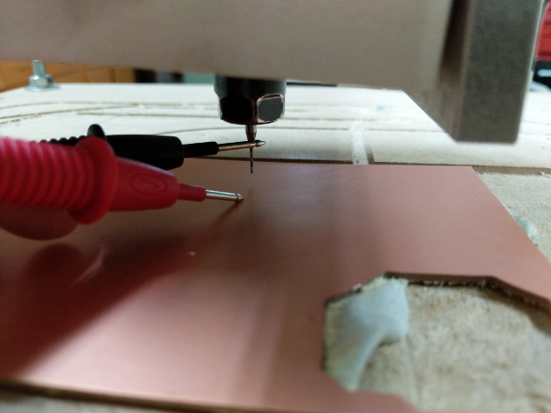
I use double side tape to fix the copper plate onto the bed. Then I set my x and y 0 and I use a multimeter to make sure of my Z 0, one probe on the copper plate, another one on the tool.
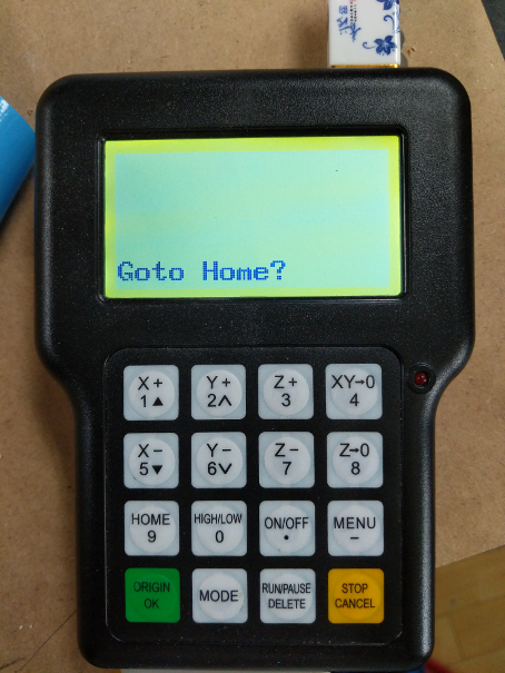
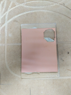
I can finally start the job and see how it goes! here are the results
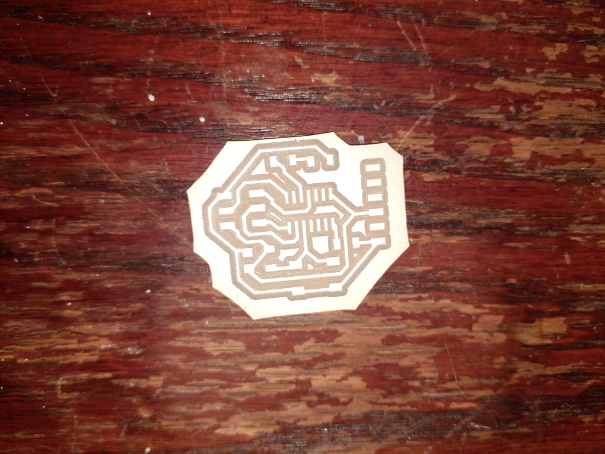
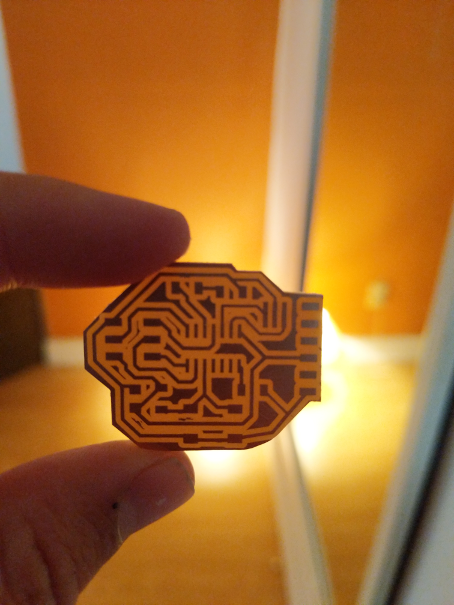
The result are great, the trace are just perfect! I use a 400 sand paper to clean the board and now were ready for soldering!
Soldering the board
Soldering PCB's can be frustrating, when your mind is not quite at it, it can seem really difficult. It may seems dumb, but I find out that having a glass of wine or a beer before soldering can help with staying relax and patient with your component.
Alays work with a good soldering Iron, and don't be afraid to take break if you starting to get impatient, listen to music or find a way to be as relax as possible. Soldering is like meditation, it's quite hard to get into the right mind set, but once your in it, everything is amazing. Always work with good light and everything will be allright.
Here are some photos of the process:
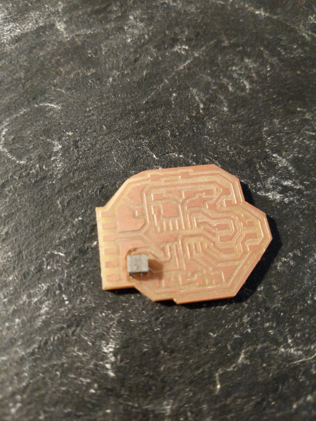
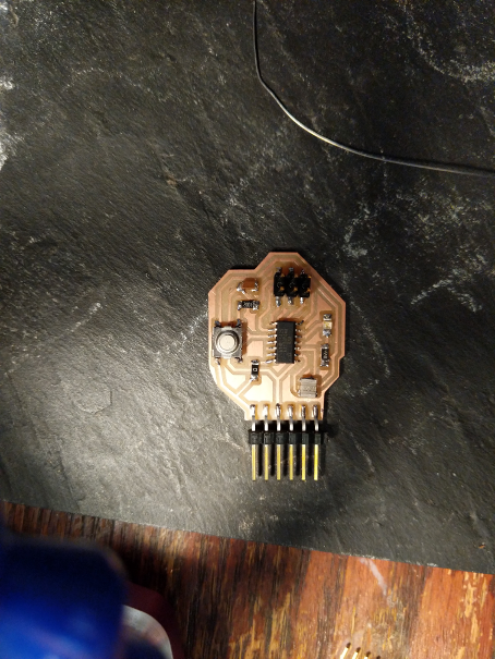
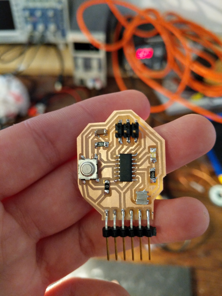
Everything seems ok! Now we'll have to wait for the embedded programming week to see if it's work!
My Files!